New Crankfire Installation Tutorial
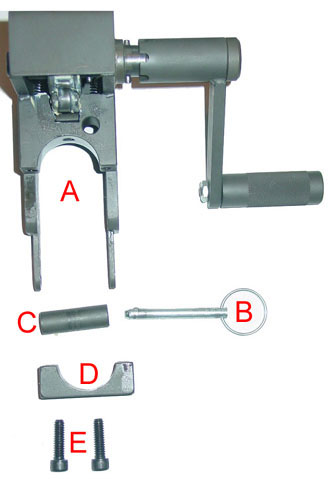
This tutorial was created to assist Crankfire owners with installation of the Crankfire unit. Since text based manuals don't provide a clear "picture" with some aspects of installation, I hope the following tutorial will be of some help.
Before beginning make sure you have the following pieces.

A. Main Crankfire Unit
B. Trigger sleeve retention pin
C. Trigger sleeve
D. Mounting collar
E. Two mounting screws
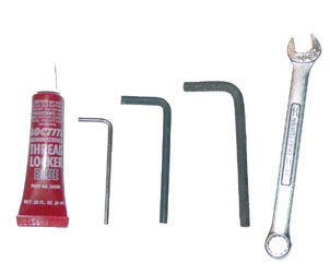
 You will also need the following tools. A Allen wrench Set, Locktite Purple (or Blue), and a 7/16ths wrench.
INSTALLATION AND OPERATION: CRANKFIRE AND ECONO CRANK UNITS
Your new Crankfire Systems unit is a simple, rugged and reliable mechanism. Please take the time to read this information and familiarize yourself with how and why these units work. Doing so will allow you to achieve the best possible performance with them.
Mounting the unit on the gun:
Both the Crankfire and the Econo Crank units are built using the same main housing and overall architecture. Initial mounting and set up are the same. Remove the two 8-32 button head alien screws on the top of the unit and slip the dust cover off. Looking in the top of the unit, right where the rocker arm lifts the trigger actuator slide, you will see a 1/4-20 adjusting screw with a jam nut, on the top of the trigger actuator slide. Using a 7/16 wrench, loosen the jam nut and back the adjusting screw out so that the rocker arm contacts the trigger actuator slide. Remove the 1/4" ball lock pin from the bottom of the trigger actuator slide and slip the trigger roller out. Remove the two 1/4-28 alien cap screws and the clamp cap from the main housing. Position the unit on the buffer tube and replace the clamp cap and screws. Leave the screws loose enough to allow the unit to be moved on the buffer tube. Position the unit fore and aft so that the trigger actuator slide/trigger roller lines up directly under the trigger arc. Twist the unit on the buffer tube so that the sides of the main housing are as nearly parallel to the receiver plates as possible. The unit housing is just a hair wider than the receiver, a small straightedge helps here. While maintaining this alignment, tighten the two 1/4-28 clamp screws securely. When installing these two screws, run them in carefully and tighten them alternately and equally. They can bind up if everything isn't aligned properly. The buffer tubes are in theory supposed to be 1 1/4" in diameter, which is the size of the mounting clamp, and round. None of them are. So on some the housing will drop around the tube easily, and on some it will have to be drawn down with the two clamp screws. There should be enough crush allowance in the clamp to hold the unit securely in place (can't be twisted on the buffer tube). At this point, check for clearance between the unit's front edges and the gun's back plate where the buffer tube intersects it. It is best if there is at least a tiny bit of "daylight" here to insure that the main housing is not in a "bind" on the back plate assy.
Adjusting the Trigger Actuator Slide:
Replace the trigger roller and the ball lock pin in the trigger actuator slide arms. There should be some space between the trigger roller and the trigger. The amount of space will vary from one gun to another due to the different trigger shapes and tolerances of the individual gun components, even when all the components are theoretically identical. To adjust this space, go back to the adjusting screw/jam nut on top of the trigger actuator slide. Run the adjusting screw down until it bears on the rocker arm and lifts the trigger actuator slide and trigger roller enough to just touch the trigger. With the gun empty, charge the bolt and rotate the crank to check that the trigger releases the sear. Also make sure that the trigger does not move too far up and bind on the back plate. If it does, backing the adjuster screw out (up) will lower the trigger roller and take care of it. The best function will be achieved when the trigger roller Is at the lowest point possible and moves "just" high enough to reliably fire the gun and no more. Time spent here "fine tuning" this adjustment is time well spent. Be sure to check this adjustment on each of the lobes individually to insure that all will fire the gun reliably as they come to bear. When the adjustment is satisfactory, retighten the jam nut on the adjusting screw. At this point, be sure to check that when the manual safety plunger is "in" blocking the rocker arm movement, that the single shot trigger will not fire the gun. NOTE: "Shot's" Rapid Fire gun didn't need a bigger roller after all. Once he was aware of the adjusting screw and used it, the unit worked fine with the original roller. Over the course of two years and 400 plus units now in use, I have had two requests for different diameter trigger rollers, one for a smaller roller and one for a larger roller. If anyone does end up with a gun/trigger combination that won't adjust out, please let me know, and I will do my best to accommodate your particular set up.
Operation of the units:
With both the Crankfire and the Econo Crank units the best performance available will be obtained by rotating the crank as smoothly as possible and at the optimum speed. Maintaining the best possible "timing" between the cam impulses and the resetting of the sear/trigger is what matters most. Any semi automatic firearm will run only as fast as that particular design allows. So out running the gun with the crank is the first concern. Almost everyone (including me) has a tendency to get carried away on the crank speed under the influence of the "Adrenaline Dump" that comes from near full auto rates of fire. Without going into all the IFs/ANDs/BUTs/Ors about what the realistic rate of fire for the typical semi auto 1919 is, suffice it to say that the full auto guns will reach something just under 500 rounds per minute on the best day. So, for the 6 lobe Crankfire this equates to 83-84 revolutions per minute and the Econo Crank a nice round 125 rpm as maximum target speeds for the crank. Both are much slower than you would think. So, please do this first, go to your handy dandy microwave and put 60 seconds on the timer. Hold the unit so you can crank it, start the timer and without watching the clock, begin cranking the unit while counting the number of revolutions. When the timer goes off, you'll be surprised how much faster you're cranking it than is required. It will take a little practice, but what you want is smooth, steady and no Warp Drive rotation of the crank.
When removing the back plate from the gun, it is not necessary to unbolt the unit. Pull the ball lock pin and remove the trigger roller. Open the top cover, retract the bolt and hold it fully to the rear. Use a long flat blade screwdriver through the clearance cut provided in the main housing clamp to turn the bolt driving spring rod to the locked position in the bolt. Push the bolt forward far enough to let the spring rod clear the back plate. Push the top cover latch forward and lift the back plate with the unit attached up out of the receiver slots.
If you wish to move the crank handle to the opposite side: On the 6-lobe Crankfire unit, Remove the dust cover, looking at the cam, you will see a 1/8" roll pin in the drive slots. Drive this pin completely out. Remove the E-clip on the end of drive shaft. Withdraw the shaft/crank assembly, the spring-loaded rocker arm will push the cam up, so a little downward pressure on the cam will help here, lift the cam out and reverse it so that the drive slots are on the side you want the crank on. While holding the cam down on the spring-loaded rocker arm, slip the shaft/crank assembly back in. Replace the E-clip and the roll pin.
The procedure for the 4-lobe Econo Crank unit is virtually the same as listed above except that there is only the one 1/8" roll pin that fixes the cam to the shaft, to be removed and replaced.
Clean and lubricate the units the same as you would the rest of the gun and use a little grease on the cam and rocker arm. The Econo Crank unit must have the cam and rocker arm well lubricated at all times, owing to it's flat tappet design.
Safety Considerations:
The 6 lobe Crankfire is equipped with both the spring loaded "Deadman" crank and the plunger type mechanical block safeties. Please do not attempt to disable either of these elements. The spring-loaded crank takes a little getting used to, but it also serves another very useful purpose. For firing short, very fast but controllable bursts, start rotating the crank in the out position, then push it over to engage the drive dogs and let it pop back out. This works times better than trying to suddenly start and stop the crank rotation with your hand. The plunger type mechanical safety was added to block the single shot thumb trigger from being unintentionally activated, it also blocks the entire operating mechanism of the unit. But both of these do not render the gun in a "safe" condition, the original trigger will still fire the gun if pushed upward.
The 4 lobe Econo Crank unit, owing to it's much simpler rotating assembly design, is equipped with the plunger type mechanical block safety only. The operation of this safety is the same on both units. When the knob is rotated to align it's lugs with the deepest notches in the threaded body, the spring load moves the plunger in, over the top of the rocker arm, preventing the upward movement required to lift the trigger actuator slide. Pulling the knob straight out and turning it 90 degrees so that it's lugs align with the shallower slots in the threaded body, moves the plunger out against the spring load, thus clearing the rocker arm and allowing it to rise and fire the gun.