Original Manuals and Tutorials
ORIGINAL CRANKFIRE INSTALLATION AND OPERATION
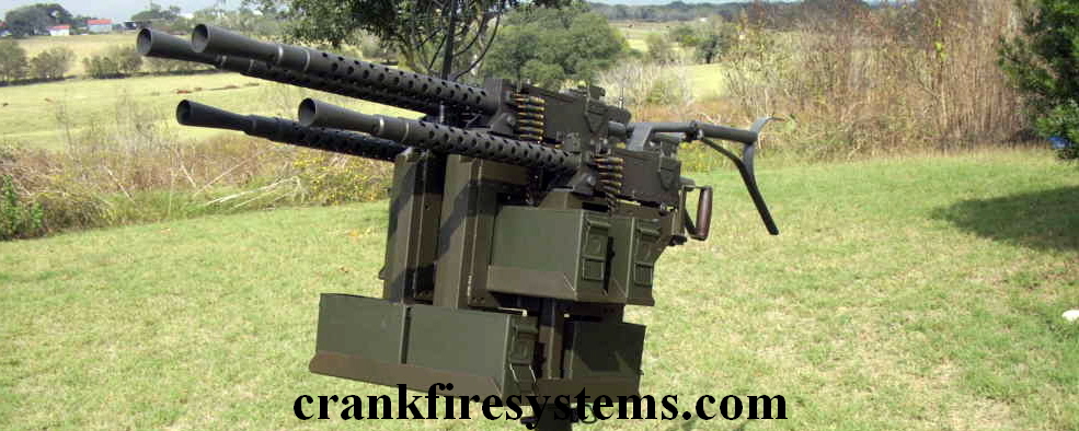
Your new Crankfire unit is a simple rugged and reliable mechanism. Please take the time to read this information and familiarize yourself with how and why the unit works. Doing so will allow you to achieve the best possible performance with it.
First a little background:
I have been involved in building and shooting crank fired semi auto twin guns since the early 90s. I saw a pair of the Calico twin gatling guns (10/22s&M1 carbine) at a gun show. Not being financially in a position to enjoy real full autos, I figured this was a way to come as close as possible. While the Calicos were neat little setups, they were designed more as a novelty item than anything else. I wanted something a bit more serious, larger caliber, higher rate of fire, larger magazine capacity, etc. The first hurdle was to increase the rate of fire from that of the two lobe cams. Yes I tried gears, I could write a book on the drawbacks of that. The next option was more lobes on the cams. But if the guns were to fire alternately, without using the Calico style in and out sliding cam system, (another book filled with grief) no matter where the crank stopped, one trigger was in the fire position or dangerously close to it. So the "floating cam" was born. You will notice that the cam used in the Crankfire floats on the drive shaft within the limits of the radial slots cut in it. This serves two functions. In the single gun application it is part of the safety system, allowing the trigger to go to the down position as soon as the crank is stopped. In a twin gun set up it allows the two guns to be phased to fire alternately and still both go to a trigger down condition when the crank is stopped. Combining the four lobe floaters with twin drum fed AR/AKs etc. I had what I wanted, over 1000 rounds per minute. That is until the semi auto beltfed 1919s came along. I just had to have a pair of these little dazzlers with a crank! Guns designed to run full bore and magazine capacity limited only by my available credit line. The 1919 presented some unique challenges; not much room around the trigger where the unit wouldn't interfere with something else and no place to mount it, without giving up the optics mount or the T&E mount, but mostly the straight up trigger pull. In short, that is why it is clamped to the buffer tube, and the cam and rocker arm are above the trigger. This allowed me to convert the rotary motion of the cam to angular motion of the rocker arm and finally get straight linear motion of the trigger slide (which the 1919 trigger really likes). I started with the four-lobe cam like the others I had used, and the gun ran quite briskly, but really jerky on the crank. I went to the six-lobe cam primarily to smooth out the crank rotation. This does how ever force you to not turn the crank too fast, it will outrun the gun in a heartbeat. The purpose of the pin type construction of the cam is that it provides the quickest possible "snap" of the trigger, allowing the maximum opportunity for the trigger disconnect to re-engage the sear for the next shot. This brings us to the discussion of crank speed. All full auto and semi auto guns can only run as fast as their particular mechanical design, pitted against the laws of physics, will allow them to. The standard 1919A4 full auto gun is rated at 500 rounds per minute give or take a few. And as I understand it, the full auto, when properly timed, actually releases the striker just BEFORE the bolt goes fully into battery. As most of us are stuck with the somewhat clumsy Lee style semi trigger, that can't release the striker until AFTER the bolt is in full battery, it is doubtful that the semi will ever reach full auto rate. I think this is why the gun seems to peak at the 460/470RPM point and then starts to actually slow down. It would appear that optimum crank speed is about 77/78 revolutions per minute, and that's a lot slower than you think it is. In all things mechanical, form must necessarily follow function, but I did want the Crankfire to look as "right" as possible when installed on the 1919s. I tried to approach this as if it were being built in the early 1900s for the military, using similar materials, shape and finish. The one concession was the ball lock pin for the trigger roller, but I figured a clevis pin with a cotter key would be a real PIA.
Well on to the step by step procedures.
Preparation of the gun and the gunner:
The change from straight semi auto operation to crank fire mode requires your gun to function at it's very best. Headspace has possibly the greatest effect on the Rate of Fire capability. Check it and make sure that it is right. If the gun runs sluggishly the first place to look is at changing the headspace slightly. A click or two can make a tremendous difference.
The semi auto triggers most commonly used in these guns, seem to suffer from reset problems frequently. The most common cure seems to be removal of .020" to .040" of material from the underside of the trigger where it contacts the bottom plate. A good trigger return spring is also required for proper operation.
The 1919 likes lots of lubrication, especially at 470RPM, so don't spare the lube on the internals. And by the way that is on "clean" internals, when you start running ammo thru it at these rates the powder residue etc. builds up in a hurry.
The booster becomes a very important item also. You will have to remove the built up carbon at much shorter intervals, and the right diameter orifice is MANDATORY.
If the booster orifice is too large the gun WILL run like a slug, and the Crankfire becomes a pointless exercise.
The numbers, as near as I have been able to determine, are:
.308-.531" 30.06-.721" 8MM-.6875"
A word about the M6 Flashider; Many people report that their semi auto guns function with these, even though the orifice is .721" for 30.06. In testing I could not get any of the crank fired guns to run with them. After I bushed them down to .531" they worked fine. As a service to those who want to use the M6 with the Crankfire, I will modify a customer-supplied flashider for $50.00. For those that can do it or have it done locally, I will be happy to tell you how mine are done.
Now for the Gunner; The most important thing here is the crank speed and the smoothness of rotation. "Everybody including me", when first firing one of these guns, instinctively wants to crank it really fast. On my AR/AK four lobe guns I have never been able to out run the guns with the crank. BUT, the 1919 semi with the six-lobe cam is a wholly different proposition. Once you exceed the 77/78 revolutions per minute on the crank the gun can't keep up and will start to "skip", and the faster you crank it the worse it gets. So PLEASE DO THIS FIRST, go to momma's microwave and put 60 seconds on the timer. Hold the Crankfire unit so that you can crank it, start the timer and without watching the clock, begin cranking the unit while counting the number of revolutions. When the timer goes off you'll be amazed at how much faster you're cranking it than is required. It will take a little practice, but what you want is Smooth, Steady and No Warp Drive rotation.
Mounting the unit on the gun:
Remove the two 8-32 button head allen screws on the top of the unit and slip the dust cover off. Remove the ball lock pin in the trigger slide bar and slip the trigger roller out. Remove the two ¼-20 allen cap screws that hold the clamp cap to the main frame. Position the unit on the buffer tube and replace the clamp cap and screws. Leave the screws loose enough to allow the unit to be moved on the buffer tube. Make sure that the unit is as far rearward as the pistol grip will allow and line the sides of the unit up parallel with the receiver plates. The unit is just a hair wider than the receiver, a little straight edge helps here. Tighten the two clamp cap screws securely. When installing these two screws, run them in carefully and tighten alternately, they can bind up if everything isn't lined up right. A word here about the buffer tubes; none of them are round nor the same size exactly. They are supposed to be 1 ¼" diameter which is the size of the hole in the main frame clamp. So on some the frame will drop around the tube easily and on some it will have to be drawn down with the two clamp cap screws. There should be enough crush allowance in the clamp to hold the unit securely in place (can't be twisted on the buffer tube). If for any reason you need to remove the rocker arm; push the trigger slide up against the springs and use a twist tie wrapped around the spring perch and the trigger slide cross bar to hold it up. On the left side of the unit there is a counter bored hole for the rocker arm pivot bolt. Use an allen wrench to remove the pivot bolt. The rocker arm can now be removed from the rear just underneath the cam. Re-assembly is essentially the reverse of disassembly with one note. When reinstalling the rocker arm pivot bolt, tighten it to just "snug", otherwise you can distort the rocker arm slot enough to cause the rocker arm to bind. Use a drop of low strength (purple) Loctite here. Now that you have the unit in place check for clearance on the front inner edges of the unit side plates where the buffer tube comes out of the gun's back plate. There are two angular clearance cuts on the side plates here that should be sufficient, but make sure there is daylight between the unit and your back plate. Re install the trigger roller and the ball lock pin in the trigger slide bar. There should be some space between the roller and the gun's trigger. The amount of space will vary from one trigger type to another and even one gun to another with identical components. To adjust this there is an adjuster screw in the trigger slide cross bar. Looking inside the unit from the top, right where the rocker arm lifts the trigger slide you will see a ¼-20 set screw with a thin jam nut. Loosen the jam nut and run the set screw down against the tip of the rocker arm to raise the trigger slide and the trigger roller until the roller just touches the trigger. Back the set screw up to lower the trigger roller so that it turns freely under the trigger. With the gun empty of course, charge the bolt and rotate the crank to check that the trigger activation releases the sear. Also make sure that the trigger does not bind up at the top of the stroke of the trigger slide/roller. If it does, use the adjuster screw to lower the slide/roller just a hair and repeat. Once you have it adjusted, lock the jam nut on the adjuster screw. Note: "Shots" Rapid Fire gun didn't need a bigger roller after all, once he used the adjuster screw it worked fine with the original roller. However if anyone does end up with a gun/trigger combination that won't adjust out, please let me know, anything can be accommodated.
Shooting time:
Some very important things are different when shooting the crank fired guns, as opposed to the slow fire semi autos; the HEAT involved goes up exponentially, especially with the air-cooled guns. So COOK OFFS become a real probability. If your gun doesn't have a bolt hold open strap, raise the top cover and pull the bolt all the way back and push the extractor down so that it catches on the cam plate on the left side and holds the bolt open. This lets air circulate thru the barrel and chamber and helps to cool it down. Please DO NOT defeat the spring-loaded "Deadman" crank. It takes a little getting used to at first and most people complain a bit, but the vast majority of the 1919 semis out there have no safety at all. Murphy's Law guarantees that if a "fixed" crank is hanging out there it WILL get bumped eventually! Ask me how I know this. The crank is spring loaded in the dis-engaged position primarily as a safety feature, but it does serve another very useful purpose. If you want to fire short, controllable, really quick bursts, start rotating the crank in the out position, then just push it over to engage the drive dogs and let it pop back out. This works way better than trying to start and stop the crank rotation quickly with your hand. DO NOT depend on the spring-loaded crank/floating cam arrangement as an absolute gun safety. It DOES NOT put the gun in a SAFE condition. It only disconnects the crank from the cam/gun trigger. To put the gun in a safe condition, you must open the top cover, remove the ammunition belt, retract the bolt to clear the chamber and lock the bolt in the open position.
Removing the back plate:
You do not have to remove the Crankfire unit in order to remove the back plate.
Pull the ball lock pin and remove the trigger roller. Open the top cover, retract the bolt and hold it fully to the rear. Use a long flat blade screwdriver through the hole provided in the main frame to turn the bolt spring rod to the locked position. Push the bolt forward far enough to let the spring rod clear the back plate. Push the top cover latch forward and lift the back plate with the unit attached up out of the receiver slots.
Reversing the crank handle:
If you want to move the crank handle to the opposite side: remove the dust cover, looking at the cam, you will see a 1/8" roll pin in the drive slots. Drive this pin completely out. There is an E clip on the end of the drive shaft. Remove this clip.
With draw the shaft/crank assembly, the spring loaded rocker arm will push the cam up, so a little downward pressure on the cam will help here, lift the cam out and reverse it so that the drive slots are on the side you want the crank on. While holding the cam down against the spring-loaded rocker, slip the shaft/crank assembly back in. Replace the E clip and the 1/8" roll pin.
Care and Feeding: Clean and lubricate the Crankfire the same as your gun. Use a little grease on the cam pins and the face of the rocker roller. Feed it LARGE quantities of .308, 30-06, 8MM or whatever you have a barrel for!!